
Pneumatic Swing Clamp - Top Flange & Threaded Body
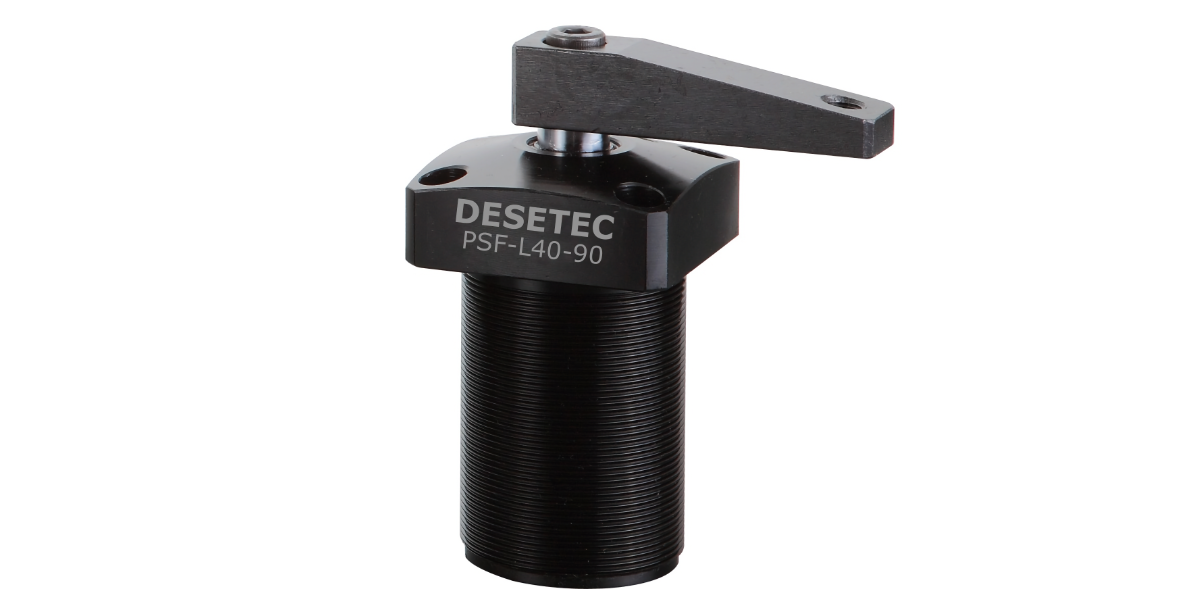
Swing clamp pneumatic screw-on with flange:
- Compact and robust pneumatic swing cylinder design
- Material: Aluminium alloy body
- Lightweight, reliable, and durable
- Top flange design for flush recessed mounting into fixtures
- Versatile mounting options via outer threaded body and flange through-holes
- Clamping forces ranging from 0.24 kN to 1.96 kN
- Supplied complete with clamping arm
- Double-acting operation
- Operating pressure: 4 to 7 bar
- Operating temperature range: −10 to +60 °C
Important Notes:
- Operating medium: Clean, filtered, oil-free compressed air.
- Customized modifications and optional swing angles (0°, 45°, 60°) available upon request!
- Direct replacement for Clamptek NPSU series
Example Ordering Code:
PSF - L 40 - 90
Series – Swing Direction – Cylinder Bore ø – Swing Angle
| ① | PSF | SERIES | PSF |
|---|---|---|---|
| ② | L | Swing Direction | R: Right (clockwise) L: Left (counter-clockwise) |
| ③ | 40 | Cylinder Bore Diameter [mm] | ø25, ø32, ø40, ø50, ø63 |
| ④ | 90 | Swing Angle | Standard: 90° (±2°) Optional: 0°, 45°, 60° (Custom angles on request) |
Specifications, CAD Data & Pricing
Technical Drawing & Dimensions [mm]
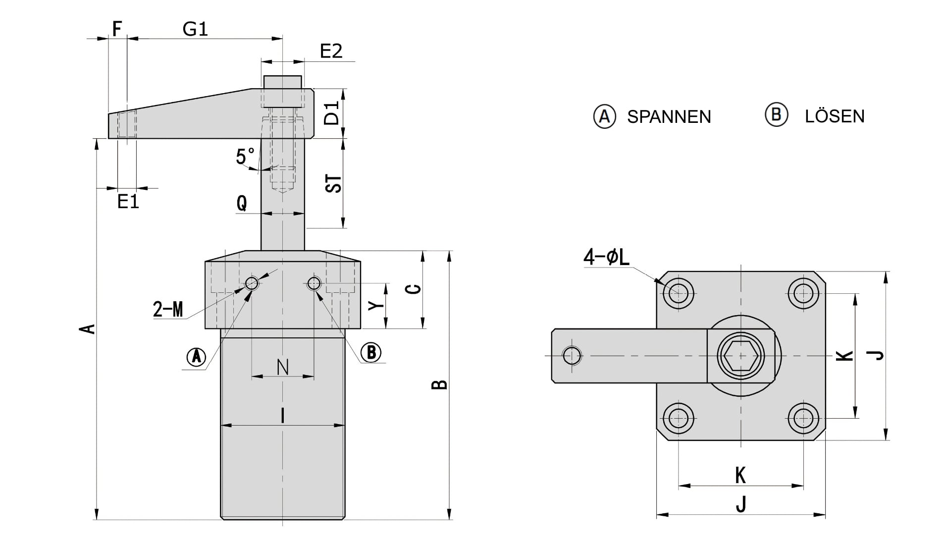
| Model | Total Stroke | A open | B | C | D1 | E1 | G1 | F | M | E2 | K | J | I | O | ØL | Y | Q |
|---|---|---|---|---|---|---|---|---|---|---|---|---|---|---|---|---|---|
| PSF-25 | 27 | 118.5 | 86.5 | 25 | 16 | M6 | 50 | 6 | M5 | M8 | 37 | 50 | M40×1.5 | 20 | 5.5-9x5.5D | 14.5 | Ø14 |
| PSF-32 | 30 | 133.5 | 97.5 | 25 | 19 | M8 | 60 | 9 | PT1/8 | M8 | 45 | 60 | M50×1.5 | 22 | 6.5-10.5x6.5D | 13 | Ø16 |
| PSF-40 | 30 | 133.5 | 97.5 | 25 | 19 | M8 | 70 | 9 | PT1/8 | M8 | 50 | 65 | M55×1.5 | 26 | 6.5-10.5x6.5D | 13 | Ø16 |
| PSF-50 | 32 | 141 | 104 | 25 | 25 | M12 | 80 | 10 | PT1/8 | M10 | 58 | 75 | M65×1.5 | 32 | 8.5-14x9D | 11 | Ø20 |
| PSF-63 | 30 | 140 | 105 | 25 | 25 | M12 | 90 | 10 | PT1/8 | M10 | 70 | 90 | M80×1.5 | 35 | 8.5-14x9D | 11 | Ø20 |
CAD Downloads PSF Series (3D STEP)
Product Datasheet
Operating, Mounting & Technical Guidelines for PSF Swing Clamps:
- Functional Principle & Stroke Sequence:
The total stroke consists of a swing stroke and a clamping stroke. At the start of clamping, the arm performs a 90° swing movement, followed by the linear down clamping travel. Important: The swinging action must never be impeded, and workpiece clamping must occur exclusively during the linear clamping travel. - Mounting & Threaded Body:
The external metric thread allows stepless height adjustment and recessed mounting into fixture plates. Fixation can be done either using a DIN 70852 slotted round nut from top or bottom, or securely from above via four socket head cap screws through the top flange. - Maintenance-Free Operation Without Oil:
Unlike standard market alternatives that mandate oil-lubricated air lines, the PSF series operates cleanly, sustainably, and completely maintenance-free using clean, filtered, unlubricated compressed air.