HLC Hydraulic Link Clamp - Hydraulic Cylinder
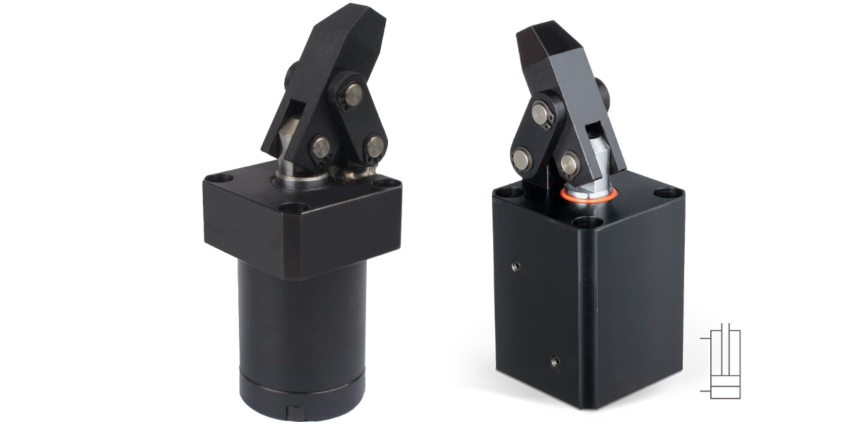
Hydraulic Link Clamp - double acting :
- compact series for use in tight places.
- Smooth inside surface structure thank to special machining processes for long durability.
- Available in block body type and flanged type.
- Clamping forces 2,52kN to 14,82kN
- complete with link mechanism and clamping arm
- double acting hydraulic cylinder
- various mounting and piping types
- Operating pressure : 10 bar - 70 bar
- Range of temperature : -10 to +70°C
- Usable fluid : Genetal hydraulic oil, equivalent to ISO-VG-32
➝ CAD-files and prices on Request !
Example ordering code:
HLC - MF 25 R A
Series – Type – Cylinder inside diameter – Lever arm direction – integrated
| ① | SERIES | HLC | |
| ② | Type | Blank: Line type M: Manifold type MF: Manifold with flow control FA: Flange type FAM: Flange with manifold type FAMT: Flange with flow control |
|
| ③ | Hydraulic cylinder Inside diameter |
25 :Ø25 mm
32 :Ø32 mm 40 :Ø40 mm 50 :Ø50 mm
63 :Ø63 mm |
|
| ④ | Lever arm direction | Blank: front (Standard) R: Right L: Left |
|
| ⑤ | integrated | - |
| Model | Clamping force at 70 bar | Clamping stroke | Total stroke | Oil capacity Clamp | Oil capacity Unclamp | eff. piston area clamp | eff. piston area unclamp |
|---|---|---|---|---|---|---|---|
| [kN] | [mm] | [mm] | [cm³] | [cm³] | [cm²] | [cm²] | |
| HLC-25 | 2,52 | 22 | 25 | 12,28 | 5,93 | 4,91 | 2,37 |
| HLC-32 | 4,12 | 22 | 25 | 20,10 | 12,25 | 8,04 | 4,9 |
| HLC-40 | 6,18 | 26 | 30 | 37,68 | 25,86 | 12,56 | 8,62 |
| HLC-50 | 9,81 | 30 | 34 | 66,74 | 45,80 | 19,63 | 13,47 |
| HLC-63 | 14,82 | 40 | 44 | 124,64 | 85,04 | 31,16 | 21,26 |
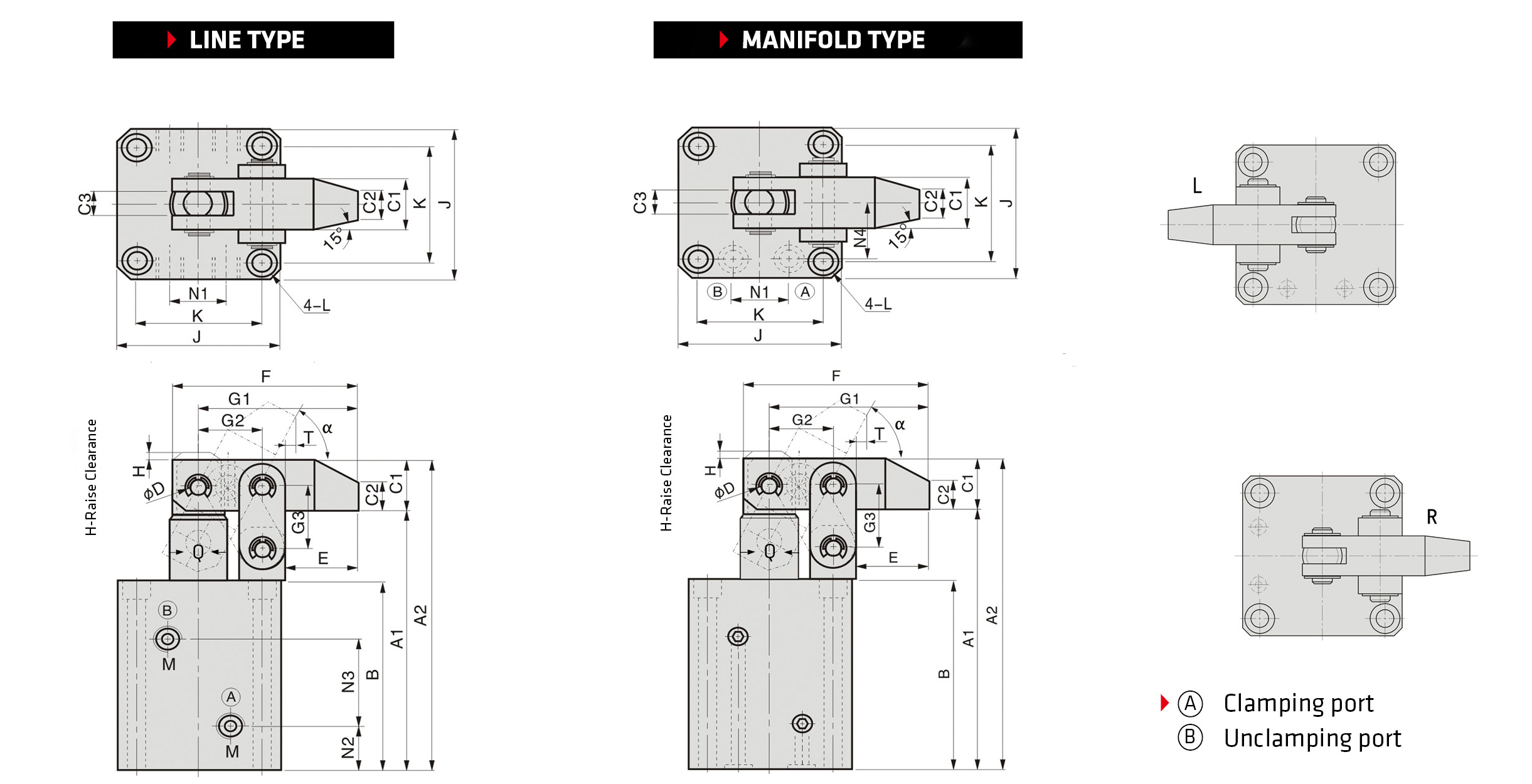
| MODEL | A1 | A2 | B | C1 | C2 | C3 | ΦD | E | F | G1 | G2 | G3 | H | J | K | L | M | N1 | N2 | N3 | N4 | O-Ring | α | T | Q |
|---|---|---|---|---|---|---|---|---|---|---|---|---|---|---|---|---|---|---|---|---|---|---|---|---|---|
| HLC-25 HLC-M25 |
103 | 122 | 76 | 19 | 11 | 9 | Φ8 | 25 | 64 | 55 | 22 | 24 | 3 | 55 | 42 | Φ6.8-Φ10.5*6.5D | PT1/8 | 18 | 17 | 33 | 20 | P7 | 61° | 4 | Ø18 |
| HLC-32 HLC-M32 |
112 | 131 | 85 | 19 | 11 | 9 | Φ8 | 25 | 64 | 55 | 22 | 24 | 3 | 57 | 44 | Φ6.8-Φ10.5*6.5D | PT1/8 | 22 | 19 | 38 | 22 | P7 | 61° | 5 | Ø20 |
| HLC-40 HLC-M40 |
122 | 144 | 90 | 22 | 13 | 10 | Φ10 | 30 | 77 | 66 | 26 | 29 | 4 | 69 | 52 | Φ9-Φ14*9D | PT1/4 | 26 | 19 | 40 | 26 | P8 | 61° | 5,5 | Ø22.4 |
| HLC-50 HLC-M50 |
137 | 162 | 100 | 25 | 15 | 11 | Φ12 | 35,5 | 90 | 77 | 30 | 33 | 4 | 75 | 58 | Φ9-Φ14*9D | PT1/4 | 32 | 21,5 | 45 | 29 | P7 | 61° | 7,5 | Ø28 |
| HLC-63 HLC-M63 |
155 | 187 | 111 | 32 | 19 | 15 | Φ15 | 43 | 110 | 94 | 36 | 39 | 4 | 96 | 75 | Φ11-Φ18*11D | PT1/4 | 38 | 22 | 52 | 38 | P9 | 66° | 2 | Ø35.5 |
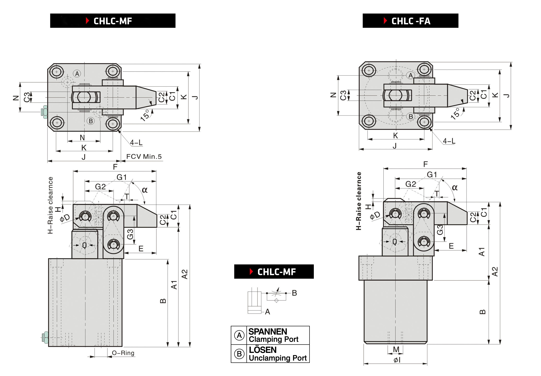
| MODEL | A1 | A2 | B | C1 | C2 | C3 | ΦD | E | F | G1 | G2 | G3 | H | J | K | L | M | N | O-Ring | α | T | Q |
|---|---|---|---|---|---|---|---|---|---|---|---|---|---|---|---|---|---|---|---|---|---|---|
| HLC-MF25 | 112 | 131 | 85 | 19 | 11 | 9 | Φ8 | 25 | 64 | 55 | 22 | 24 | 3 | 55 | 42 | Φ6.8-Φ10.5x6.5D | - | 19 | P7 | 61° | 4 | Ø18 |
| HLC-MF32 | 115 | 134 | 88 | 19 | 11 | 9 | Φ8 | 25 | 64 | 55 | 22 | 24 | 3 | 57 | 44 | Φ6.8-Φ10.5x6.5D | - | 21 | P7 | 52° | 11 | Ø20 |
| HLC-MF40 | 130 | 152 | 98 | 22 | 13 | 10 | Φ10 | 30 | 77 | 66 | 26 | 29 | 4 | 69 | 52 | Φ9-Φ14x9D | - | 23 | P9 | 58° | 7,5 | Ø22.4 |
| HLC-MF50 | 145 | 170 | 108 | 25 | 15 | 11 | Φ12 | 35,5 | 90 | 77 | 30 | 33 | 4 | 75 | 58 | Φ9-Φ14x9D | - | 28 | P9 | 61° | 7,5 | Ø28 |
| HLC-MF63 | 163 | 195 | 119 | 32 | 19 | 15 | Φ15 | 43 | 110 | 94 | 36 | 39 | 4 | 96 | 75 | Φ11-Φ18x11D | - | 35 | P9 | 66° | 2 | Ø35.5 |
| MODEL | A1 | A2 | B | C1 | C2 | C3 | ΦD | E | F | G1 | G2 | G3 | H | ΦI | J | K | L | M | N | O-Ring | α | T | Q |
|---|---|---|---|---|---|---|---|---|---|---|---|---|---|---|---|---|---|---|---|---|---|---|---|
| HLC-FA25 | 49 | 131 | 63 | 19 | 11 | 9 | Φ8 | 25 | 64 | 55 | 22 | 24 | 3 | Φ45 | 55 | 42 | Φ6.8-Φ10.5x6.5D | PT1/4 | 25 | - | 61° | 4 | Ø18 |
| HLC-FA32 | 52 | 134 | 63 | 19 | 11 | 9 | Φ8 | 25 | 64 | 55 | 22 | 24 | 3 | Ø50 | 57 | 44 | Φ6.8-Φ10.5x6.5D | PT1/4 | 32 | - | 61° | 5 | Ø20 |
| HLC-FA40 | 57 | 152 | 73 | 22 | 13 | 10 | Φ10 | 30 | 77 | 66 | 26 | 29 | 4 | Ø58 | 69 | 52 | Φ9-Φ14x9D | PT1/4 | 40 | - | 61° | 5,5 | Ø22.4 |
| HLC-FA50 | 67 | 170 | 78 | 25 | 15 | 11 | Φ12 | 35,5 | 90 | 77 | 30 | 33 | 4 | Ø68 | 75 | 58 | Φ9-Φ14x9D | PT1/4 | 50 | - | 61° | 7,5 | Ø28 |
| HLC-FA63 | 74 | 196 | 90 | 32 | 19 | 15 | Φ15 | 43 | 110 | 94 | 36 | 39 | 4 | Ø82 | 98 | 75 | Φ11-Φ18x11D | PT1/4 | 63 | - | 66° | 2 | Ø35.5 |
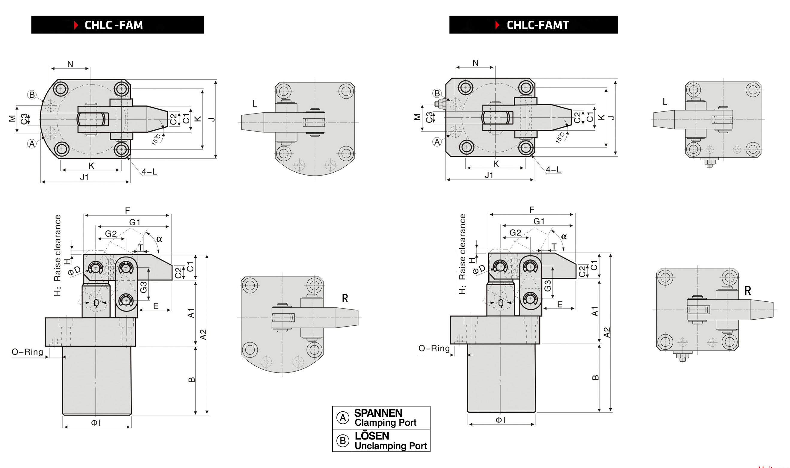
| MODEL | A1 | A2 | B | C1 | C2 | C3 | ΦD | E | F | G1 | G2 | G3 | H | ΦI | J | J1 | K | L | M | N | O-Ring | α | T | Q |
|---|---|---|---|---|---|---|---|---|---|---|---|---|---|---|---|---|---|---|---|---|---|---|---|---|
| HLC-FAM25 | 49 | 122 | 54 | 19 | 11 | 9 | Φ8 | 25 | 64 | 55 | 22 | 24 | 3 | Φ45 | 55 | 64 | 42 | Φ6.8-Φ10.5x6.5D | 20 | 28 | P6 | 61° | 4 | Ø18 |
| HLC-FAM32 | 52 | 131 | 60 | 19 | 11 | 9 | Φ8 | 25 | 64 | 55 | 22 | 24 | 3 | Φ50 | 57 | 65,5 | 44 | Φ6.8-Φ10.5x6.5D | 22 | 29 | P6 | 61° | 5 | Ø20 |
| HLC-FAM40 | 57 | 144 | 65 | 22 | 13 | 10 | Φ10 | 30 | 77 | 66 | 26 | 29 | 4 | Φ58 | 69 | 79 | 52 | Φ9-Φ13.5x9D | 25 | 34,5 | P9 | 61° | 5,5 | Ø22.4 |
| HLC-FAM50 | 67 | 162 | 70 | 25 | 15 | 11 | Φ12 | 35,5 | 90 | 77 | 30 | 33 | 4 | Φ68 | 75 | 87 | 58 | Φ9-Φ13.5x9D | 30 | 39 | P9 | 61° | 7,5 | Ø28 |
| HLC-FAM63 | 74 | 187 | 81 | 32 | 19 | 15 | Φ15 | 43 | 110 | 94 | 36 | 39 | 4 | Φ82 | 98 | 114 | 75 | Φ11-Φ18x11D | 40 | 49,5 | P9 | 66° | 2 | 35,5 |